Appendix 1: Types of construction and applications
Slab
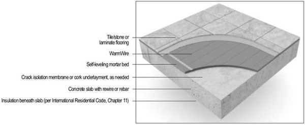
The cross sections on these pages depict types of construction (slab vs. frame floor) and applications commonly used in the installation of the cable. Choose the best installation detail for the particular construction and application.
Slab Construction and Applications
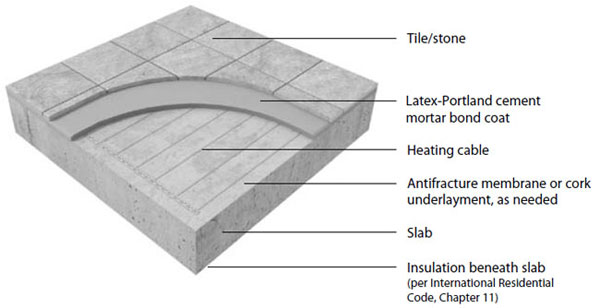
Insulation. In new slab construction, it is highly recommended that foam insulation be installed under and around the slab to pre vent loss of radiant heat into the surrounding soil.
In existing construction where insulation under the slab is absent, it is strongly recommended that a layer of insulating material be attached to the slab prior to the installation of the cable.
Cork, for example, possesses a minimal R value that will help keep the radiant heat at the floor surface. Consult the cork manufacturer regarding proper application and attachment of the cork to the concrete slab. There are other options for insulation as well.
Anti fracture membrane. While optional, it is recommended that an anti fracture membrane be installed directly to the slab or the self-leveling mortar layer underneath the tile. This flexible layer reduces the chance of minor stress and fracturing in the slab from being transmitted upward to the tile
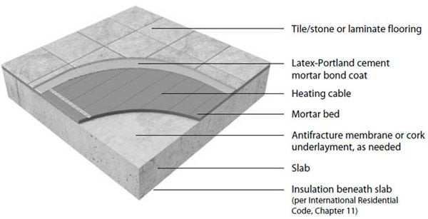
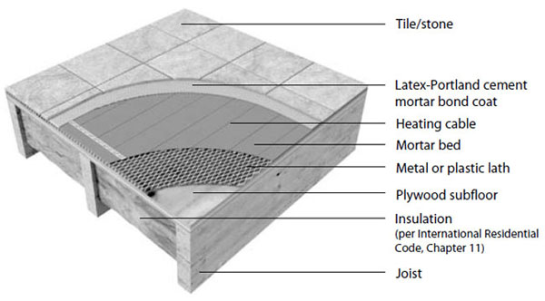
Reinforcement. To further strengthen the floor, consider laying a 1-1/4″ to 2″ mud bed, reinforced with metal or plastic lath, directly onto the optional anti fracture membrane. Then install the cable(s).
1. Thin-set mortar over slab
(Dry-set or latex cement on slab; TCA # RH115-03)
2. Thick-set Mortar bed Over slab
(cement mortar bonded; TCA # F112-03)
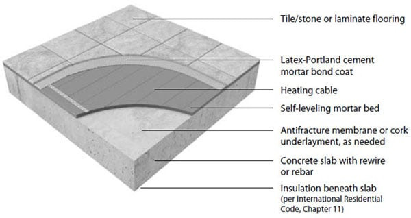
3. Self-leveling mortar over slab on grade
Framed floor
Framed Floor Construction and Applications
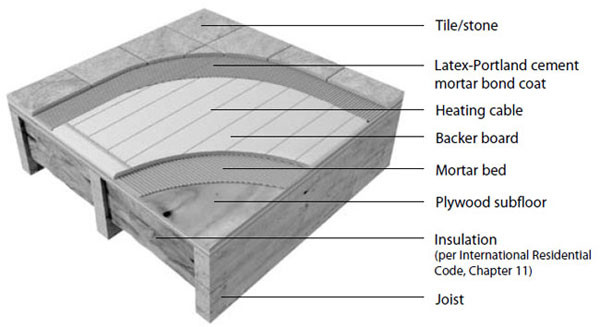
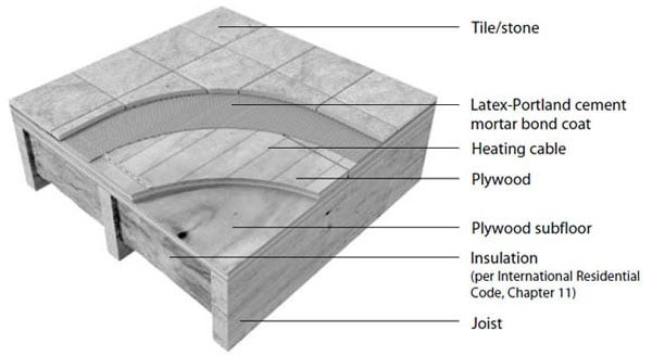
In framed-floor construction, the two primary concerns are insulation and floor rigidity. Without proper insulation, radiant heat leaks into the joist spaces. And unless the plywood sub floor is properly rein forced, stresses in the sub flooring can cause unsightly cracking in the tile floor.
Insulation. The use of insulation in the joist spaces dramatically enhances the performance and efficiency of the floor-warming system.
Insulation with an R value of 19 will be sufficient for most regions, while in more temperate areas R-1 1 will suffice.
Do not install rigid insulation layers directly above or below backer board or mortar. If possible, install insulation as shown in the diagrams at right.
Reinforcement. There are several options for strengthening the subfloor:
1. Add 3/4-thick plywood on top of the existing subfloor.
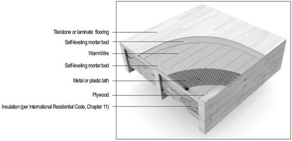
2. Pour a 1/4″ – 1/2″-thick layer of self-leveling mortar over the existing subfloor, then install the cables on top of the mortar layer.
3. Install a quality cementitious backer board or fiber cement underlayment over the subfloor.
Then install the cable and lay the tile.
Anti fracture membrane. While optional, it is recommended that an anti fracture membrane be installed to reduce the chance of minor stress and fracturing in the sub flooring from being transmitted upward to the tile. If an anti fracture membrane is used, install the cable above the membrane, unless otherwise recommended by the membrane manufacturer.
In place of an anti fracture membrane, an uncoupling system can be installed to prevent deflection in the subfloor from affecting the tile surface.
Mortar Beds
The cables can be installed in three types of mortar beds: thin-set or thick-set mortar beds 3/8″ to 1″ thick, and self-leveling mortar beds 1/4″ to 1/2″ thick
Thin set Mortar Beds If the cable will be placed directly onto the slab, or if backer board or plywood reinforcement is used on a plywood subfloor, first install the cable then apply the thin-set mortar bond coat directly over the cable and lay the tile.
Thick-set Mortar Beds. If a thicker mortar bed is used to strengthen the floor, the cable can be installed under either the mortar bed (also known as “dry-set”) or under the mortar bond coat directly below the tile or stone. In a thick-set application, the cable is generally installed above the mortar bed, but before the thin- set bond coat. Thick mortar beds of this type require the use of a reinforcing mesh or lath
4. Thin-set mortar over framed floor
(Dry-set or latex cement on slab; TCA # F144-03)
5. Thin-set mortar over framed floor
(Dry-set or latex cement mortar; TCA # RH130-03)
6. Thick-set cement mortar with lath
(Cement mortar metal lath; TCA #145-03)
SELF-LEVELING APPLICATIONS
6. SELF-LEVELING MORTAR OVER FRAME FLOOR
7. SELF-LEVELING MORTAR OVER SLAB ON GRADE
If plastic lath is used instead of the typical metal lath, the cable can be installed before pouring the self-leveling mortar bed.
CAUTION: If metal lath is used in the mortar bed, do not allow the cable to come in direct
contact with the lath. Damage to the cable could result.
Self-leveling Mortar Applications: Self-leveling mortar beds are appropriate if installing non-masonry floor coverings such as engineered wood, vinyl, laminate, or carpet. Attach the cables to the slab or subfloor, then pour a 1/4″ – 1/2″ thick layer of self-leveling mortar over the cables according to manufacturer’s specifications.
Install the floor coverings after the mortar has cured.
Regardless of the type of mortar bed used in any particular application, always secure the cable to the floor first, then cover it with the mortar or cement. Never attempt to lay or work the cable into a previously-poured layer of wet mortar.
It is strongly recommended that tile and stone flooring be installed according to manufacturer’s recommendations, Tile Council of North America (TCNA) guidelines, and ANSI specifications. Follow industry and manufacturer’s recommendations when installing non-masonry floor coverings, such as hardwood, vinyl, laminate, or floating floors.
Other Considerations
Expansion joints. In slab or mortar applications, do not install the cables through an expansion joint unless an appropriate anti fracture membrane is installed per TCA recommendations. If not
using an anti fracture membrane, install the cables right up to the joint, if necessary, but not through the joint.
Mosaic tile. When laying mosaic tile, first embed the cables in the appropriate mortar bed as
shown in the diagrams on the previous pages, and allow to cure per manufacturer’s instructions.
Then thin-set the mosaic tile according to typical practice.
If installing WarmWire in self-leveling mortar over a frame floor, you must first stiffen the floor. Install floor covering after the mortar has cured.
In this application, WarmWire is generally installed above the self-leveling mortar in a thin-set bond coat.
If you use plastic lath instead of the typical metal lath, the WarmWire can be installed in the self-leveling mortar bed.
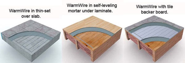
WarmWire can be installed in two general types of construction applications:
1. Thin-set or thick-set mortar beds (3/8″ – 1″) over slabs or framed floors.
2. Self-leveling mortar beds (1/4″ – 1/2″) over slabs or framed floors.
Always install WarmWire before installing mortar or cement. Do not lay WarmWire in wet mortar. We strongly recommend installing tile and stone flooring according to
manufacturer’s recommendations, TCA guidelines, and ANSI specifications.
If installing non-masonry floor coverings, the best method is cover the WarmWire in a self-leveling mortar.
Then install floating floors, vinyl, laminate or carpet, per industry and manufacturer’s recommendations.
Thin-set or Thick-set Mortar Applications: There are several types of thin-set and thick-set mortar applications illustrated below and on the following pages.
a. If backer board or plywood sheeting is used to strengthen the floor, or if the mat will be placed directly onto the slab, install WarmWire in the thin-set mortar bond coat above these materials.
b. If a thicker mortar bed is used to strengthen the floor, WarmWire can be installed in either the mortar bed (dry-set) or in the mortar bond coat directly below the tile or stone.
WarmWire design and sizing considerations
WarmWire can be used to warm the floor in areas as small as a powder room or as large as an entire home.
There really is no limit. A single cable can heat areas as large as 240 sq. ft. Even larger rooms can be warmed with multiple cables wired in parallel.
WarmWire can provide all the heat necessary for a room, as well as just warm the floor. It delivers over 40 BTUH per square foot, which is quite a bit of heat.
Most rooms need far less than this. So, if you have a room where you want WarmWire to be the sole source of heat, it will likely do the job.
Simply calculate the room’s heat loss and compare it to the output of WarmWire shown on the next page.
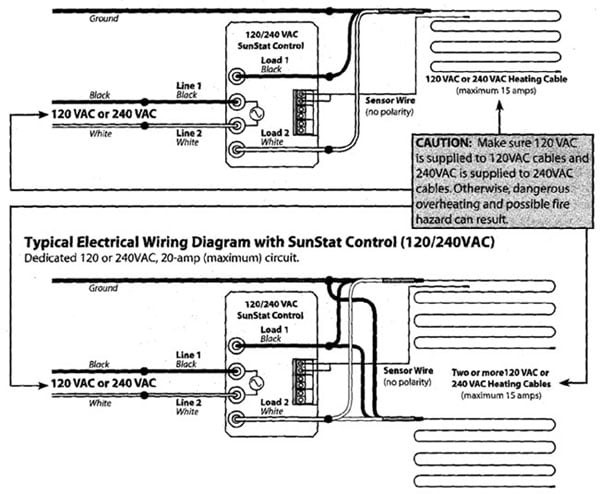
CAUTION: Make sure 120 VAC is supplied to 120 VAC and 240 VAC is supplied to 24OVAC mats. Otherwise, dangerous overheating and possible fire hazard can result
All electrical work must be done by a qualified licensed electrician in accordance with local building and electrical codes, and the National Electrical Code (NEC), especially Article 424, Part IX of the NEC, ANSI/NFPA7O and Section 62 of CEC Part 1.
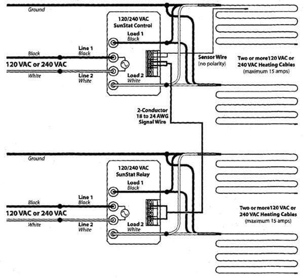
Appendix:2 Typical Electrical Wiring Diagrams 120/240 Volt
Typical Electrical Wiring Diagram with SunStat Control (120 and 240 Volt)
Dedicated 120 or 240VAC. 20-amp (maximum) circuit.
Typical Electrical Wiring Diagram with SunStat Control and Relay(s)
Dedicated 120VAC or 240VAC. 20-amp (maximum) circuit.
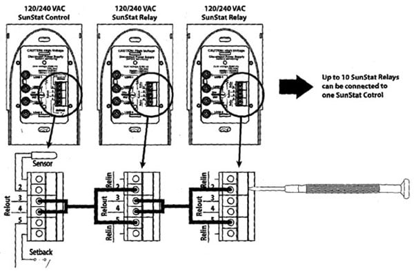
Diagram for connection of signal wire between SunStat Control and Relays
CAUTION: Make sure 120 VAC is supplied to 120 VAC and 240 VAC is supplied to 24OVAC mats.
Otherwise, dangerous overheating and possible fire hazard can result
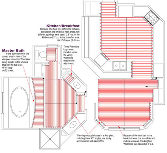
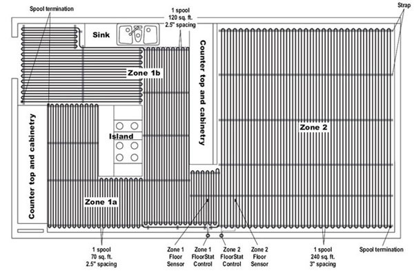
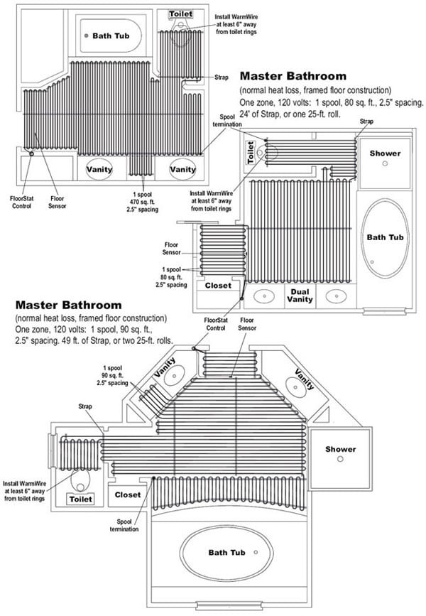
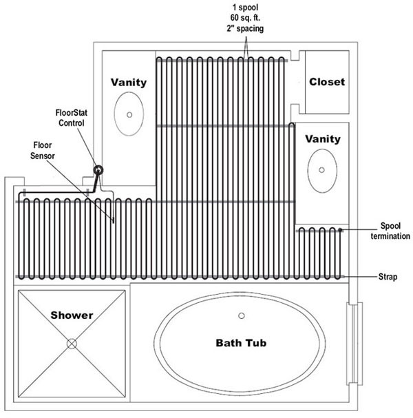
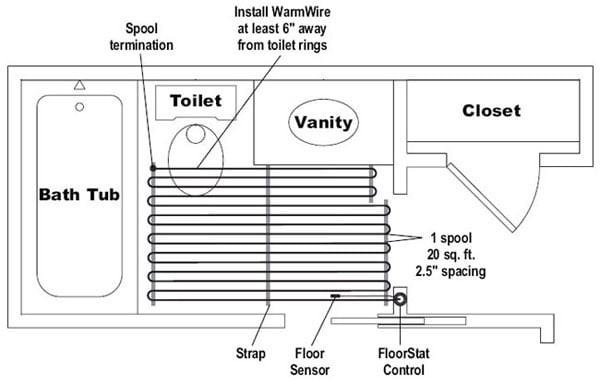
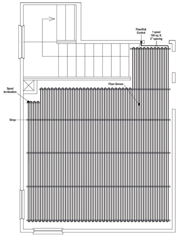
Appendix 5: Sample WarmWire Layouts
Kitchen and Family Room (normal heat loss, on-grade slab)
Two zones, 240 volts:
Kitchen/Zone 1a = 1 spool, Zone 1b = 1 spool, 120 sq. ft., 2.5″ spacing.
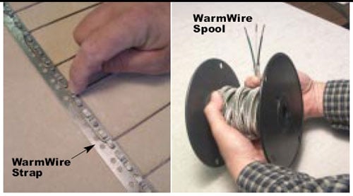
Family Room/Zone 2 = 1 spool, 240 sq. ft., 3″ spacing 190 ft. of Strap, or eight 25-ft. rolls.
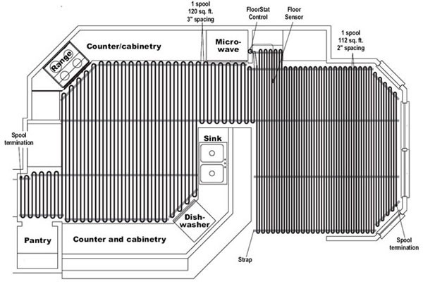
Kitchen and Sunroom (normal and high heat loss, framed floor construction)
Two zones, 240 volts:
Kitchen/Zone 1a = One zone, 240 volts: Kitchen = 1 spool, 120 sq. ft., 2.5″ spacing.
Sunroom = 1 spool, 112 sq. ft., 2″ spacing. 104 ft. of Strap, or five 25-ft. rolls.
Master Bathroom (normal heat loss, framed floor construction)
One zone, 120 volts: 1 spool, 470 sq. ft., 2.5″ spacing. 35 ft. of Strap, or two 25-ft. rolls.
Appendix: Sample WarmWire Layouts
Basement Bathroom (high heat loss, below grade basement slab)
One zone, 120 volts: 1 spool, 60 sq. ft., 2″ spacing. 39 ft. of Strap, or two 25-ft. rolls.
Master Bathroom (normal heat loss, framed floor construction)
One zone, 120 volts: 1 spool, 20 sq. ft., 2.5″ spacing. 11′ of Strap, or one 25-ft. roll.
Recreation Room (high heat loss, below grade basement slab)
One zone,240 volts: 1 spool, 160 sq. ft., 2″ spacing. 69 ft. of Strap, or three 25-ft. rolls.
WarmWire™ Features:
• Single point connection
• Insulated with high-performance ETFE
• Strengthened with Aramid reinforcing
• Protected with stainless steel jacket
• Available in both 120 VAC and 240 VAC
• Sizes available up to 240 sq. ft.
• UL Listed in Canada and the USA
• Ultra-low EMF
• Grounded from one end to the other
Enjoy your new SunTouch WarmWire floor-warming system!
Click here for SunTouch VIDEO Library
SunTouch vs. Product A – SunTouch vs. Product B
SunTouch Floor Heating Mat Links
SunTouch Mats Spec and installation – SunTouch Mat Specification – Underfloor Spec and Installation
SunTouch Floor Heating Spool Links
SunTouch WarmWire Installation Guidelines – SunTouch WarmWire Strap – WarmWire Installation Guidelines – WarmWire Order Instruction and Information
Heating Controls Links
Programmable SunStat Spec – Owner’s Manual Programmable 500670-SB – Owner Manual Non Programmable 500675
– SunStat Non Programmable Spec – SunStat Relays Control – LoudMouth Operating Instruction
Misc SunTouch Links
SunTouch 25 year Limited Warranty – EMF Electromagnetic fields – Frequently Asked Questions – Repair Heating Wire – Suntouch Low Price Guarantee
Today is my lucky day 🙂
I like the layout of your website.
How-do-you-do, just wanted you to know I have added your site to my Google bookmarks because of your extraordinary blog layout. But in earnest, I think your site has one of the freshest theme I’ve came across. It really helps make reading your blog a lot simpler.
Thanks for the great post. I always like to bookmark concrete or construction related posts like this one.
I would love to know if this blog will be continued.
TILE ME! Our downstairs bathroom is in serious need of some new tiles. As is our kitchen. I tile on the wall in there looks like bricks in a prison!
You really make it appear so easy along with your presentation but I find this topic to be actually something that I believe I might by no means understand. It sort of feels too complicated and very vast for me. I’m looking ahead for your next put up, I will try to get the dangle of it!
I can’t find specific instructions about calculating the exact length required, and layout for a particular room. In fact, you should have a computer based design program that would tell spacing and length of wire, and print it out for the installation crew..
Use this link for our Floor Heating Calculator
https://www.flooringsupplyshop.com/index.php?main_page=calculator